
In this guide
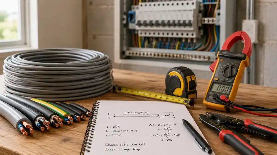
Choosing an electrical cable is not simply a matter of matching one current value to one cable size. The correct cross-sectional area depends on the load, supply voltage, cable length, conductor material, installation method, ambient temperature, protective device and the voltage drop allowed by local rules and the connected equipment.
This guide and the HomDera calculator provide a preliminary sizing estimate, not approval for an electrical installation. Final cable selection, protective-device coordination, earthing and fault-protection checks should be completed by a qualified electrician or electrical designer using the rules that apply in your location.
What size electrical cable do I need?
Cable size is a system decision
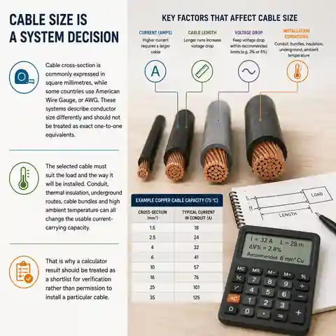
Cable cross-section is commonly expressed in square millimetres, while some countries use American Wire Gauge, or AWG. These systems describe conductor size differently and should not be treated as exact one-to-one equivalents.
The selected cable must suit the load and the way it will be installed. Conduit, thermal insulation, underground routes, cable bundles and high ambient temperature can all change the usable current-carrying capacity.
That is why a calculator result should be treated as a shortlist for verification rather than permission to install a particular cable.
Why cable size cannot be chosen by amps alone
Current is the starting point, but it is only one part of cable sizing. The same current can require a different conductor size when the route is longer, the cable is surrounded by insulation, several circuits are grouped together, aluminium is used instead of copper or a motor has a high starting current.
Information needed before choosing a cable
| Input | Why it matters | What to verify |
|---|---|---|
| Design current | Determines the continuous electrical load the circuit must carry | Use the actual load, nameplate data or a justified demand calculation |
| Cable length | Longer conductors have more resistance and therefore more voltage drop | Measure the real route, not only the straight-line distance |
| Supply voltage and phase | The current and voltage-drop formulas differ for DC, single-phase and three-phase systems | Confirm the nominal system voltage and circuit type |
| Conductor material | Copper and aluminium have different resistance, termination and sizing requirements | Use data for the actual material, not a generic table |
| Installation method | A cable in free air dissipates heat differently from one in conduit, insulation or the ground | Identify the complete route and the most restrictive section |
| Ambient temperature and grouping | Heat and nearby loaded circuits can reduce effective current-carrying capacity | Apply the correction factors required by the relevant standard |
| Protective device | The breaker or fuse must protect the cable against overload and fault conditions | Check rating, trip characteristics and fault-disconnection requirements |
| Connected equipment | Motors, compressors, pumps and electronic equipment may have starting or inrush current | Review manufacturer instructions and operating conditions |
Two cables with the same nominal cross-section can have different current ratings because their insulation, number of loaded conductors, construction and installation conditions are not identical.
Step 1: determine the design current
When the equipment nameplate provides current in amperes, that value is usually a better starting point than calculating from advertised power alone. If only power is known, current can be estimated from voltage, but power factor, efficiency and starting behaviour may also matter.
Approximate current for a resistive single-phase load:
I = P_in / V

Single-phase estimate from electrical input power:
I = P_in / (V × PF)

Single-phase estimate from output power:
I = P_out / (V × PF × η)

Balanced three-phase estimate from electrical input power:
I = P_in / (√3 × V_LL × PF)

Balanced three-phase estimate from output power:
I = P_out / (√3 × V_LL × PF × η)

Where:
I = line current in amperes
P_in = electrical input power in watts
P_out = useful output or mechanical power in watts
V = single-phase supply voltage in volts
V_LL = line-to-line voltage in volts
PF = power factor
η = efficiency as a decimal
For heaters and other mainly resistive loads, power factor and efficiency may be close to 1. Motors, pumps, air conditioners, compressors and some electronic loads need more careful treatment because their running current, power factor and starting current may differ significantly from a simple watts-to-amps estimate.
A 3,600 W resistive appliance operates from a 230 V single-phase supply. What is the approximate running current?
Answer: 3,600 W ÷ 230 V = 15.65 A, so the estimated running current is about 15.7 A.
Explanation: This calculation identifies the approximate load current only. It does not select the cable because length, installation conditions, voltage drop, protective device and local requirements still need to be checked.
Step 2: coordinate the cable with the circuit breaker or fuse
A protective device is not chosen independently of the cable. In a simplified design check, the circuit design current should not exceed the protective-device rating, and the protective-device rating should not exceed the cable's corrected current-carrying capacity.
Simplified coordination check:
Ib ≤ In ≤ Iz

Ib = design current of the circuit
In = rated current or setting of the protective device
Iz = cable current-carrying capacity after applicable corrections
The value of Iz must reflect the real installation, not only a catalogue value under reference conditions. Temperature, thermal insulation, grouping, conduit fill, underground installation and the number of loaded conductors can require correction factors that reduce the usable capacity.
- Cable enclosed in thermal insulation
- Several loaded circuits installed together
- High ambient or ground temperature
- A long section inside conduit or trunking
- Underground installation with unfavourable soil conditions
- Multiple loaded cores within the same cable
- Equipment with long operating periods or high starting current
Do not solve nuisance tripping by fitting a larger breaker unless the cable, terminals, earthing arrangement and fault protection have been checked. A higher-rated breaker can remove the protection that the existing cable relied on.
Step 3: account for cable length and voltage drop
Every conductor has resistance. As current travels through the cable, part of the supply voltage is lost along the route. The effect becomes more important when current is high, the conductor is small, the cable is long or the system voltage is low. Excessive voltage drop can cause poor equipment performance, difficult motor starting, dim lighting, additional heating and wasted energy.
Simplified resistive voltage-drop estimate for a two-conductor path:
ΔV = (2 × L × I × ρ) / S

Voltage drop percentage:
ΔV% = (ΔV / V) × 100

L = one-way cable length in metres
I = load current in amperes
ρ = conductor resistivity in Ω·mm²/m
S = conductor cross-section in mm²
V = nominal supply voltage
This simplified formula is useful for understanding the effect of length and cross-section, but a final AC calculation may also need conductor operating temperature, reactance, power factor, cable construction and the correct single-phase or three-phase method. For DC battery systems, include the complete positive-and-negative current path.
How does conductor size affect voltage drop for a 25 A load on a 30 m one-way copper run at 230 V?
Answer: Using a simplified resistivity value of 0.0175 Ω·mm²/m at 20°C, a 4 mm² conductor gives an estimated drop of about 6.56 V, or 2.85%. A 6 mm² conductor gives about 4.38 V, or 1.90%.
Explanation: The larger cross-section has lower resistance, so the voltage drop is smaller. These figures are illustrative only: operating temperature, installation method, AC characteristics, protective-device coordination and local voltage-drop limits still need verification.
Illustrative voltage-drop comparison
| Copper cross-section | Estimated resistance of 60 m loop | Drop at 25 A | Percentage of 230 V |
|---|---|---|---|
| 4 mm² | 0.2625 Ω | 6.56 V | 2.85% |
| 6 mm² | 0.1750 Ω | 4.38 V | 1.90% |
Maximum permitted voltage drop varies by country, circuit type and application. Lighting, motors, sensitive electronics, low-voltage DC systems and long feeders may need different design targets. A low calculated voltage drop does not by itself prove that the cable is correctly sized.
Step 4: choose the conductor material and cable type
Copper and aluminium conductors
| Factor | Copper | Aluminium |
|---|---|---|
| Electrical resistance | Lower resistance for the same cross-section | Higher resistance, so a larger cross-section is often needed for the same duty |
| Size and flexibility | Usually more compact and often easier to terminate in small equipment | Larger conductors can be economical for feeders and higher-current applications |
| Connections | Requires terminals suitable for copper | Requires aluminium-rated terminals, correct preparation and compatible connection methods |
| Weight and cost | Heavier and often more expensive | Lighter and may reduce conductor cost in suitable applications |
| Substitution | Must be sized from copper data | Must be sized from aluminium data; do not replace copper with the same nominal cross-section automatically |
The conductor is only one part of the cable. Insulation temperature rating, number of cores, flexibility, mechanical protection, fire performance, moisture resistance, sunlight resistance and permitted installation environment also matter. Use a cable type approved for the intended location and compatible with the equipment terminals.
Step 5: check the installation conditions
- Will the cable be clipped in open air, inside conduit, behind a wall or buried?
- Does any part of the route pass through thermal insulation?
- Will it be grouped with other loaded power cables?
- What ambient temperature can occur around the cable?
- Is the cable exposed to moisture, sunlight, chemicals or mechanical damage?
- How many conductors are expected to carry current at the same time?
- Are fire-resistant, low-smoke or other special cable properties required?
- Can the selected cable bend and terminate correctly at both ends?
The most restrictive part of the route can determine the whole circuit design. For example, a cable may run mainly in free air but pass through a short insulated section where heat cannot escape. That section should not be ignored simply because most of the route has better cooling.
A safer cable-sizing workflow
- Identify the appliance, circuit or group of loads and record the manufacturer data.
- Calculate or confirm the design current, including power factor, efficiency, duty cycle and starting current where relevant.
- Confirm the supply voltage, phase arrangement and earthing system.
- Measure the actual one-way route and note every installation method along it.
- Select a preliminary cable type and conductor material suitable for the environment.
- Check corrected current-carrying capacity against the load and protective device.
- Calculate voltage drop and review equipment-specific limits.
- Verify short-circuit withstand, earth-fault protection, disconnection time, protective conductor size and terminal compatibility.
- Have the final design and installation checked according to local electrical rules.
Use the calculator to compare preliminary options. If increasing the length, current or temperature changes the suggested cross-section, that is a useful sign that the installation needs a closer design check rather than a guess from a generic chart.
What not to do when selecting cable size
- Do not choose a cable from appliance power alone without converting the load correctly.
- Do not use a current table without checking its installation method and reference conditions.
- Do not ignore cable length because the circuit breaker is nearby.
- Do not assume copper and aluminium of the same cross-section are interchangeable.
- Do not increase the breaker rating to stop repeated trips without investigating the cause.
- Do not conceal undersized conductors inside walls, insulation or inaccessible junctions.
- Do not mix AWG and mm² values as though they are exact equivalents.
- Do not rely on cable colour or outside diameter to identify conductor cross-section.
- Do not use a flexible cord as a permanent substitute for fixed-installation cable unless it is specifically permitted for that application.
- Do not treat a calculator result as a replacement for testing and inspection.
Practical example: planning a new high-power appliance circuit
A 5,500 W resistive appliance will be installed 22 m from a 230 V distribution board. Can the cable size be selected from the power rating alone?
Answer: No. The approximate running current is 5,500 ÷ 230 = 23.9 A. That value is only the first input. The designer must also check the actual route, installation method, cable material, corrected current-carrying capacity, breaker rating, voltage drop, fault protection and the appliance manufacturer's instructions.
Explanation: A generic chart may suggest a candidate cross-section, but the same 23.9 A load can require a different solution when the cable is grouped, surrounded by insulation, installed in a hot area, routed over a longer distance or connected to equipment with special requirements.
When an electrician or electrical designer is needed
- A new fixed circuit, distribution board or subpanel is being installed
- The load includes a cooker, water heater, boiler, heat pump, air conditioner, EV charger, workshop machine, pump or motor
- The route is long, buried, outdoors, grouped or enclosed in thermal insulation
- Aluminium conductors or transitions between aluminium and copper are involved
- The circuit is three-phase, DC battery-based, solar-related or supplied by an inverter or generator
- The existing breaker trips, a cable or plug becomes warm, lights dim or equipment starts poorly
- The available fault current, earthing arrangement or protective-device operation is unknown
- Local rules require design, testing, certification or notification by an authorised person
Stop using the circuit and arrange an inspection if there is a burning smell, discolouration, melted insulation, crackling, arcing, repeated breaker operation or unusual heating at cables, plugs, sockets or terminals.
Cable size checklist before installation
- Load current is based on reliable equipment data
- Starting and inrush current have been considered where relevant
- Supply voltage and phase are confirmed
- The full cable route has been measured
- Conductor material and cable type match the application
- Installation method and correction factors have been applied
- The breaker or fuse coordinates with the corrected cable capacity
- Voltage drop has been checked for the complete route
- Protective earthing and fault-disconnection requirements have been verified
- Terminals are suitable for the conductor size and material
- The result complies with local rules and manufacturer instructions
- The completed circuit will be inspected and tested before normal use
Frequently asked questions
Can I choose cable size only from watts?
No. Watts can be converted into an approximate current when voltage and other electrical characteristics are known, but cable length, voltage drop, installation method, conductor material, protective device and local rules still affect the final size.
Does a longer cable need to be thicker?
Often it does. A longer route increases resistance and voltage drop. Upsizing the conductor can reduce the drop, but the final choice must still satisfy current-carrying capacity, protection and installation requirements.
Is copper cable always better than aluminium?
Not in every application. Copper is compact and has lower resistance for the same cross-section, while aluminium can be lighter and economical for suitable larger circuits. Aluminium normally needs a larger cross-section and requires compatible terminals and installation methods.
Can I use the next larger cable size?
A larger conductor can reduce voltage drop and provide additional thermal margin, but it must fit the equipment terminals, protective device and installation system. Larger is not automatically correct if the cable cannot be terminated properly or the rest of the circuit design is unsuitable.
Why does an electrical cable become warm?
Some temperature rise is normal when current flows, but excessive heat can indicate overload, an undersized conductor, poor ventilation, loose or unsuitable terminals, damaged cable or a fault. Unusual heating should be investigated rather than accepted as normal.
How do AWG and mm² cable sizes compare?
AWG is a gauge system in which a smaller gauge number generally means a larger conductor. Square millimetres describe the conductor's cross-sectional area directly. Because common AWG sizes do not exactly match common metric sizes, use an approved conversion reference and then verify the electrical rating for the actual cable and installation method.
Use a cable size result as a starting point, not a guarantee
A useful cable size estimate combines load current, route length, voltage, conductor material and an allowed voltage-drop target. A complete design goes further by checking actual installation conditions, protective devices, fault current, earthing, termination and local electrical requirements. Use the HomDera calculator to compare preliminary options, then have the selected circuit verified before purchase or installation.
Open the HomDera Cable Size CalculatorCalculate the combined electrical load of household appliances