
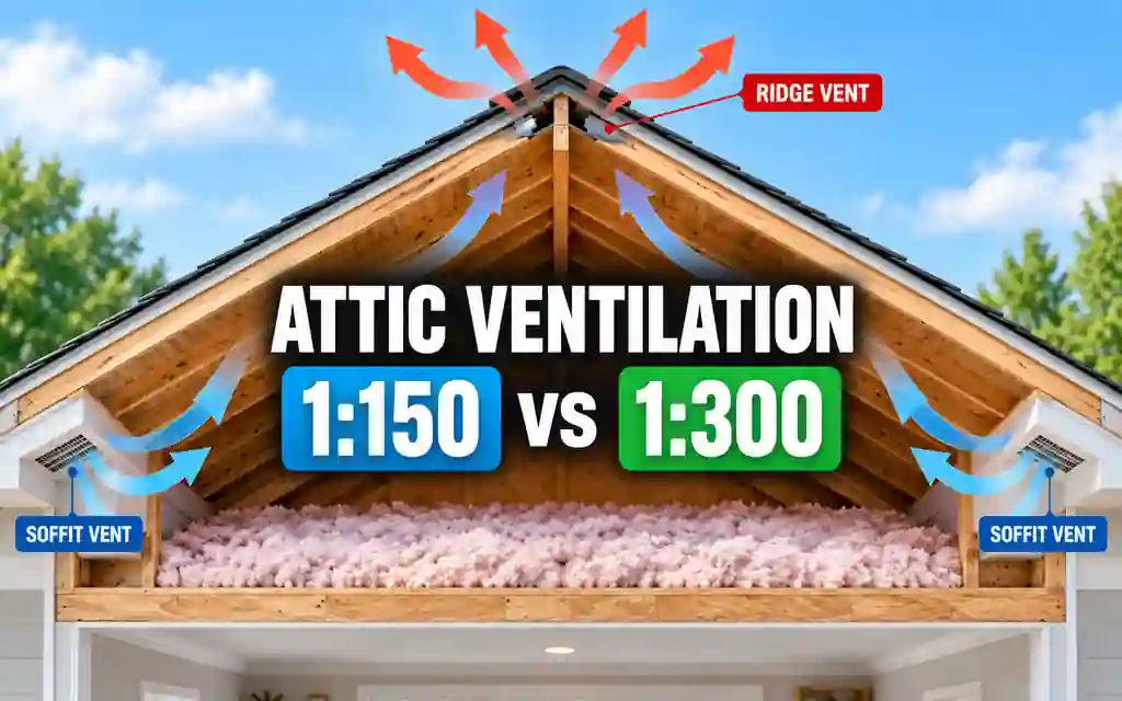
Attic ventilation sounds simple until three numbers appear on the same page: 1:150, 1:300 and NFA. Then a soffit vent is sold by linear feet, a ridge vent has a different airflow rating, and somebody suggests adding two box vents because the roof already has holes for them. The calculation is not difficult, but the pieces need to be kept in the right order.
This guide explains the common US code-style method for naturally ventilated attics: how the 1:150 and 1:300 ratios differ, what Net Free Area actually means, why intake and exhaust should be balanced, and how to convert a square-inch NFA target into a realistic soffit and ridge-vent layout. It also explains where the method stops being useful, because a sealed conditioned attic is not simply a vented attic with the vents forgotten.
Quick answer: 1:150 requires 1 square foot of Net Free Ventilating Area for every 150 square feet of vented attic space. The 1:300 method requires half as much vent area, but it is an exception rather than an automatic shortcut. Under the IRC-style approach, the required high/low distribution must be met, and cold-climate vapor-retarder conditions also matter.
The 1:150 and 1:300 ratios are US model-code concepts, not universal worldwide rules. Building codes are adopted and amended locally, and other countries use different roof-ventilation and condensation-control methods. Use this guide for the calculation logic, then check the code, roof-system instructions and climate requirements that apply to the actual building.
From attic area to a balanced vent layout
What Attic Ventilation Is Actually Trying to Do
A conventional vented attic uses openings low in the roof and openings high in the roof to exchange attic air with outdoors. In a common soffit-to-ridge arrangement, outside air enters at the eaves, travels through a clear path above the insulation and leaves near the ridge. The purpose is not to make the attic feel like an outdoor porch. It is to help manage heat and moisture in a roof assembly that is intentionally designed to be vented.
What ventilation can help with — and what it cannot repair
| Issue | What ventilation can do | What still needs its own fix |
|---|---|---|
| Moisture in a vented attic | Support drying and moisture removal when intake, exhaust and airflow paths are correct | Indoor humidity sources, ceiling air leakage, roof leaks and missing vapor-control details |
| Summer attic heat | Provide a path for outdoor air exchange through the vented space | Insulation level, solar heat gain, duct losses and air-conditioning design |
| Cold-climate roof conditions | Support the intended cold-roof ventilation strategy | Air sealing, insulation continuity, snow/ice conditions and the actual roof design |
| Blocked eaves | Nothing, if air cannot pass the insulation | Baffles, vent chutes and a clear opening from the soffit into the attic |
| Bathroom fan dumping into the attic | It cannot make that a good idea | The exhaust duct must be properly routed to an approved outdoor termination |
NFA and NFVA: The Number That Matters on the Vent Label
NFA means Net Free Area, and NFVA means Net Free Ventilating Area. In everyday attic-ventilation calculations the terms are commonly used for the effective unobstructed airflow area through a vent after louvers, screens, filters, internal ribs and other restrictions are taken into account. A vent that measures 8 × 16 inches on the outside does not automatically provide 128 square inches of usable airflow.
Gross opening size is not the same as Net Free Area
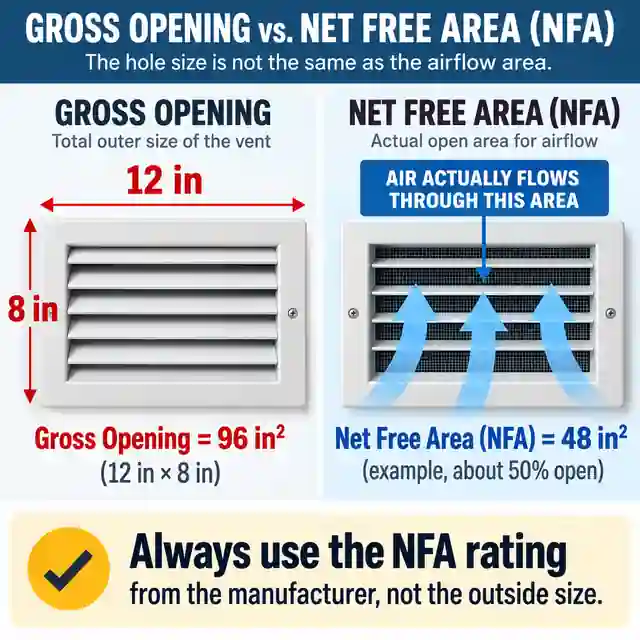
The outside dimensions tell you how large the vent assembly is.
NFA or NFVA tells you how much effective open area the manufacturer assigns to that product.
Continuous ridge and soffit products are often rated in square inches of NFA per linear foot.
Individual roof or gable vents are commonly rated in square inches of NFA per vent.
Always use the rating for the exact model, not a visually similar product.
The 1:150 Rule: The General Starting Point
In the IRC model-code approach, the general minimum Net Free Ventilating Area is 1/150 of the area of the vented space. For a simple attic with a flat ceiling below it, that normally means the attic floor or ceiling-plan area, not the larger sloped area of the roof covering.
1:150 total NFA

Total NFA (ft²) = vented attic area (ft²) ÷ 150
Total NFA (in²) = vented attic area (ft²) ÷ 150 × 144

Example:
1,200 ft² ÷ 150 × 144 = 1,152 in² total NFA
The 1:300 Rule: Why It Is Not Just the Cheaper Button
The 1:300 ratio halves the total vent area, which is why it appears attractive on a shopping list. But the reduced ratio is an exception with conditions. Under the 2021 IRC wording, the required ventilation must be distributed between the upper and lower portions of the attic, with 40–50% of the required area in the upper portion. In Climate Zones 6, 7 and 8, a Class I or II vapor retarder on the warm-in-winter side of the ceiling is also part of the exception. Local amendments can change the details, so the adopted code controls.
1:150 vs 1:300 in practical terms
| Question | 1:150 | 1:300 |
|---|---|---|
| Status in the IRC-style calculation | General baseline | Reduced-area exception |
| Total NFA for a 1,200 ft² attic | 1,152 in² | 576 in² |
| High/low placement | A balanced intake/exhaust layout is still good practice and commonly required by roof-system guidance | The exception depends on the prescribed upper/lower distribution |
| Cold Climate Zones 6–8 | No reduced-ratio exception is being claimed | The IRC exception includes the specified warm-side Class I or II vapor retarder condition |
| Can you select it only to buy fewer vents? | No special reduction is being used | No — verify that the exception conditions and local requirements are actually satisfied |
Do not assume that every modern roof automatically qualifies for 1:300. A contractor, calculator or product chart may use 1:300 as a common design basis, while the adopted local code or the actual roof assembly may require something different.
Measure the Vented Attic Area, Not the Shingle Area
For a typical vented attic above a flat ceiling, use the plan area of the attic space. If the house is 40 ft × 30 ft and that whole footprint belongs to one connected vented attic, the calculation area is 1,200 ft². Roof pitch makes the shingle surface larger, but it does not turn that attic into a larger floor plan. Complex roofs can contain separate cavities, so do not combine spaces that cannot actually exchange air.
What does 1:150 versus 1:300 mean for the same 1,200 ft² attic?
Answer: At 1:150, the attic needs 1,152 in² of total NFA. At 1:300, it needs 576 in². If the 1:300 layout is split evenly for planning, that is 288 in² of intake and 288 in² of exhaust. The same ratio works mathematically in metric units: 100 m² at 1:300 equals about 0.333 m², or 3,333 cm², of total net free area — but the US ratio should not be treated as a local compliance rule outside jurisdictions that use it.
Explanation: The ratio is dimensionless: area is divided by 150 or 300. The product conversion comes afterward, using the NFA rating of the selected vent.
Balance Intake and Exhaust Before Counting Products
A useful natural-ventilation layout does not begin by filling the ridge with exhaust and asking the eaves to keep up later. Intake and exhaust are one system. A 50/50 NFA split is a practical planning target, while the IRC 1:300 exception places 40–50% of the required NFA high in the attic and the balance low. Many roofing manufacturers also warn against providing more ridge-exhaust NFA than the available soffit intake can support.
How to read a balanced NFA target
| Total required NFA | Approx. low intake target | Approx. high exhaust target |
|---|---|---|
| 480 in² | 240 in² | 240 in² |
| 576 in² | 288 in² | 288 in² |
| 720 in² | 360 in² | 360 in² |
| 1,152 in² | 576 in² | 576 in² |
The useful airflow path is low in and high out
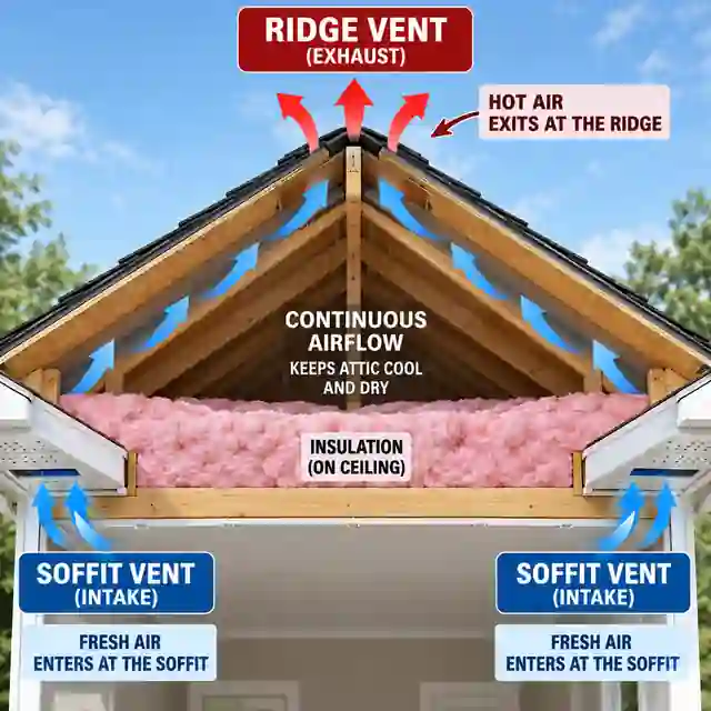
Soffit or eave vents provide low intake.
A clear channel above the insulation lets air move into the attic or rafter space.
Ridge or other approved high vents provide exhaust near the top of the roof.
The path should remain continuous; a vent hidden behind packed insulation contributes very little to the system you thought you bought.
Separate attic compartments need their own workable intake and exhaust paths.
Soffit Vents: Intake Is Usually Where the Layout Gets Lost
Continuous perforated soffit, strip vents and individual soffit vents can all provide intake when they are part of an approved roof detail. The important number is their listed NFA. If a continuous soffit product provides 9 in² of NFA per linear foot and the attic needs 288 in² of low intake, the mathematical minimum is 32 linear feet of that product in total. The layout still has to distribute that intake sensibly along the eaves and connect it to a clear air path.
- Do not count solid soffit panels as ventilation just because the roof has generous overhangs.
- Do not use the gross perforated-panel area instead of the manufacturer's NFA rating.
- Check whether insulation, blocking, paint, insect mesh or stored material obstructs the opening.
- Spread intake rather than concentrating it in one convenient corner of a long attic.
- Where the roof has multiple isolated eave sections, make sure each relevant cavity actually connects to the exhaust path.
- If there is no usable soffit, choose an intake strategy that is specifically designed for that roof rather than inventing a slot.
Ridge Vent: Convert Exhaust NFA Into Usable Ridge Length
Ridge vents are commonly rated in square inches of NFA per linear foot. That makes the conversion simple: divide the required exhaust NFA by the product's listed NFA per foot. The result is the minimum vented ridge length for that product, before checking end clearances, hips, intersecting roofs, structural limitations and the manufacturer's installation instructions.
Required ridge-vent length = exhaust NFA target ÷ ridge-vent NFA per linear foot

Example:
288 in² exhaust ÷ 18 in²/ft = 16 ft of ridge vent
How much ridge vent is needed for a 1,200 ft² attic using 1:300 and a ridge product rated at 18 in² NFA per linear foot?
Answer: The total 1:300 target is 576 in². Using an even planning split gives 288 in² of high exhaust. Dividing 288 by 18 gives 16 linear feet of that ridge vent.
Explanation: A different ridge vent can have a different NFA per foot. One current GAF ridge product, for example, is listed at 21.5 in² per linear foot, while other products use lower ratings. Product-specific NFA is why the vent length should be calculated from the exact technical sheet.
If the calculation needs 24 ft of ridge vent but the roof has only 16 ft of usable ridge, the solution is not to type 16 into the shopping list and congratulate the roof for becoming smaller. Check a higher-NFA approved product or a properly designed alternative exhaust strategy.
Usable ridge length can be less than the visible ridge. Intersections, short ridge segments, end restrictions, chimneys and manufacturer termination details may reduce the length that can actually be vented. Check the roof geometry before selecting a product solely from its NFA rating.
Box Vents, Static Vents and Ridge Vents Are Exhaust Options — Not Collectibles
A static roof vent can be converted from NFA in the same way: divide the exhaust target by the listed NFA per vent and round up to complete units. That does not mean a roof needs a complete ridge-vent system plus the full calculated quantity of box vents. Different exhaust types can alter the intended airflow path, and existing vents should be reviewed as a system rather than treated as free bonus capacity.
Common high-exhaust options
| Vent type | How it is usually rated | Planning note |
|---|---|---|
| Continuous ridge vent | NFA per linear foot or metre | Works best when paired with adequate low intake and installed to the roof-system detail |
| Box/static roof vent | NFA per individual vent | Count whole units and distribute them in the appropriate high roof area |
| Gable vent | NFA per vent | Its airflow pattern differs from a dedicated soffit-to-ridge layout; do not assume it combines perfectly with every roof system |
| Turbine vent | Product-specific rating and performance data | Wind-driven behaviour is not identical to a simple static NFA calculation |
| Powered attic fan | Airflow in CFM or m³/h plus intake requirements | This is a mechanical airflow problem and should not be sized from passive NFA alone |
Do not add exhaust devices simply because each one sounds useful. A full ridge vent plus existing box vents, turbines or powered fans can create an airflow pattern that differs from the intended low-to-high path. Follow the roofing and vent manufacturers' compatibility guidance or a project-specific design.
Baffles and Vent Chutes Keep the Soffit From Disappearing Behind Insulation
A soffit vent can have an excellent laboratory NFA and still contribute almost nothing if loose-fill insulation is piled against the roof deck at the eave. Baffles or vent chutes are used in many vented roof assemblies to preserve a clear channel from the eave into the attic or along a rafter bay. The required clearance and baffle detail depend on the roof assembly and applicable code.
The vent needs an air path, not just an opening
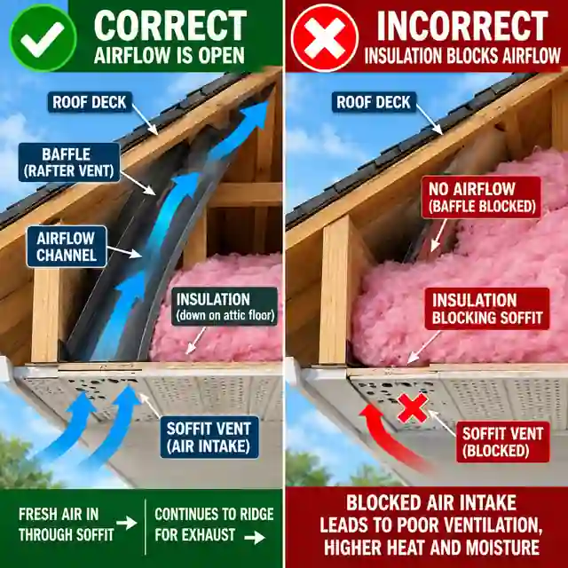
The soffit opening brings air into the eave.
An insulation dam helps keep loose material away from the opening.
The baffle preserves a clear channel beside the roof deck where the design requires one.
Insulation should remain continuous over the ceiling without choking the intake.
A beautiful row of soffit vents is not useful if every opening ends in a wall of fiberglass.
Ventilation Does Not Replace Attic Air Sealing
One of the most important distinctions in attic work is the difference between air moving through the ventilation system and conditioned indoor air leaking through the ceiling. Recessed lights, wiring penetrations, plumbing stacks, attic hatches, partition tops and duct openings can carry warm moist indoor air into a cold attic. Adding roof vents does not make those leaks disappear.
- Condensation or frost repeatedly appearing near ceiling penetrations
- Dark staining around roof nails or sheathing without an obvious roof leak
- Insulation that is disturbed, dirty or damp around air-leak paths
- An attic hatch with visible gaps or no weather-sealing
- Bathroom or kitchen ducts terminating inside the attic
- Large temperature differences around leaky ducts running through the attic
- Soffit vents present outside but completely buried by insulation inside
Bathroom, toilet-room and kitchen exhaust should not be discharged into the attic. Mechanical exhaust air belongs at an approved outdoor termination. Attic ventilation is not a substitute exhaust duct.
A Conditioned or Unvented Attic Is a Different Roof Assembly
Not every roof should have soffit and ridge vents. Some assemblies are intentionally designed as unvented or conditioned attics, with insulation and air-control layers at the roof deck and specific moisture-control details. Adding ventilation openings to such an assembly can defeat the design. Before retrofitting vents, identify where the building's thermal and air boundaries actually are.
Vented attic vs intentionally unvented attic
| Feature | Conventional vented attic | Conditioned/unvented attic |
|---|---|---|
| Typical insulation location | At or above the ceiling plane | At the roof deck or another designed roof-envelope layer |
| Outdoor ventilation openings | Part of the intended assembly | Normally not added unless the assembly specifically calls for them |
| Attic temperature | Outside the conditioned thermal envelope | Closer to indoor conditions when the attic is inside the envelope |
| Main calculation in this guide | Potentially applicable | Not the correct design method |
| Before changing the assembly | Check NFA, airflow path, air sealing and insulation | Check the complete unvented-roof design, materials, climate and code requirements |
Do not drill or cut new ventilation openings into a spray-foamed, conditioned or otherwise intentionally unvented roof because a generic attic calculator says the NFA is zero. Zero may be exactly what that assembly was designed to have.
US, UK and Other English-Speaking Markets Use Different Ventilation Language
The physics of a clear intake-to-exhaust path travels well; the compliance numbers do not. In the United States, attic, soffit, ridge vent and NFA/NFVA are common terms. In the UK and Ireland you will often see loft, eaves ventilation and ridge ventilation, and requirements are commonly expressed through local condensation-control guidance and equivalent continuous opening areas rather than an IRC 1:150 or 1:300 rule. Australia, New Zealand and Canada also have their own codes, climate provisions and product systems.
Useful vocabulary when searching product data
| Term in this guide | Other terms you may see | What to verify |
|---|---|---|
| Attic | Loft, roof space | Which enclosed space is actually being ventilated |
| Soffit intake | Eaves vent, fascia intake, low-level ventilation | Listed free area and connection to the roof space |
| Ridge vent | High-level ventilation, continuous ridge ventilation | NFA/free area per unit length and installation detail |
| NFA / NFVA | Net free vent area, equivalent free area in some product literature | The exact definition used by the local standard and manufacturer |
| 1:150 / 1:300 | IRC-style vent ratio | Do not assume it is the local compliance method outside the relevant US code context |
Complete Example: 1,200 ft² Attic, 1:150 vs 1:300
Same attic, two ventilation ratios
| Calculation | 1:150 | 1:300 |
|---|---|---|
| Attic floor area | 1,200 ft² | 1,200 ft² |
| Total NFA | 1,200 ÷ 150 × 144 = 1,152 in² | 1,200 ÷ 300 × 144 = 576 in² |
| 50% planning intake | 576 in² | 288 in² |
| 50% planning exhaust | 576 in² | 288 in² |
| Ridge vent at 18 in² NFA/ft | 32 ft | 16 ft |
| Soffit vent at 9 in² NFA/ft | 64 ft total | 32 ft total |
| Important condition | General ratio used in the calculation | Use only when the applicable exception conditions are satisfied |
What if the ridge vent provides 12.5 in² per foot instead of 18 in²?
Answer: For the 1:300 example, the exhaust target remains 288 in². At 12.5 in² per foot, 288 ÷ 12.5 = 23.04 ft, so the project needs at least about 23.1 ft mathematically and should be converted into the product's actual installation lengths and termination rules. For 1:150, 576 ÷ 12.5 = 46.08 ft.
Explanation: The attic requirement did not change; only the product's NFA changed. That is why copying a ridge-vent length from another house is unreliable even when the attic areas match.
Common Attic Ventilation Calculation Mistakes
Mistake, result and better check
| Mistake | What goes wrong | Better approach |
|---|---|---|
| Using sloped roof area | The vent target is overstated for a typical flat-ceiling attic | Use the vented attic floor/ceiling-plan area where the method applies |
| Selecting 1:300 automatically | Required NFA can be understated by half | Confirm the exception conditions and adopted local code |
| Using vent dimensions instead of NFA | Louvers and screens are treated as open air | Use the exact listed NFA/NFVA |
| Sizing exhaust before intake | High vents can exceed the low intake available | Plan intake and exhaust as one system |
| Blocking soffits with insulation | The calculated intake exists only on paper | Maintain the required clear eave airflow path |
| Adding every exhaust type together | Air can short-circuit between high vents or behave differently from the intended layout | Use a compatible exhaust strategy |
| Ignoring separate roof cavities | One well-vented attic is assumed to ventilate another enclosed space | Calculate and detail each connected vented space |
| Using passive NFA to size a powered fan | Fan airflow and makeup-air requirements are ignored | Use the fan/system design method |
| Assuming ventilation fixes indoor moisture | Air leakage or exhaust problems remain | Air-seal and control moisture sources as part of the roof strategy |
| Adding vents to an unvented roof | The designed air/thermal control layers can be undermined | Identify the roof assembly before modifying it |
Useful Technical References
For US projects, start with the residential code actually adopted by the local jurisdiction, then compare it with the roofing and vent manufacturers' current instructions. The links below are useful reference points for the model-code method and for seeing how product NFA changes the required vent length.
ICC: 2021 IRC R806.2 — minimum vent area and the 1:150 / 1:300 exceptionGAF: attic ventilation calculator and product-specific intake/exhaust examplesFrequently Asked Questions
Is more attic ventilation always better?
No. The goal is a correctly designed, balanced and unobstructed system, not the largest possible collection of vents. Extra exhaust without matching intake can change the airflow path, and mixing incompatible vent types can reduce the effectiveness of the layout. Follow the adopted code and the selected roof-system instructions.
Are NFA and NFVA the same thing?
They are commonly used for the same practical sizing concept: the net unobstructed area available for ventilation after restrictions in the vent are accounted for. Product literature may prefer one abbreviation. Use the manufacturer's listed value and units for the exact vent.
Can I use soffit vents if the roof has no ridge vent?
Soffit vents can provide low intake, but a vented attic also needs an appropriate high exhaust path. If a continuous ridge vent is not possible, static roof vents or another approved exhaust method may be used depending on the roof design. Do not reduce the required exhaust simply because the ridge is short or absent.
Final Attic Ventilation Check Before Buying Vents
- The roof assembly is intentionally vented; it is not a conditioned or unvented attic.
- The calculation uses the correct vented attic/ceiling-plan area rather than shingle area.
- The 1:150 or 1:300 ratio matches the adopted local requirements and roof design.
- Any conditions required for the 1:300 exception have been verified rather than assumed.
- Total NFA has been converted into a realistic low-intake and high-exhaust target.
- Every selected vent uses the NFA or NFVA from its exact technical sheet.
- The soffit/eave intake is physically open and distributed where the roof needs it.
- Baffles or vent chutes preserve the airflow path where insulation meets the eaves.
- The ridge has enough usable length for the selected ridge-vent NFA, or another approved exhaust strategy has been designed.
- Existing box vents, gable vents, turbines or powered fans have been considered before adding a new exhaust system.
- Bathroom, kitchen and other mechanical exhaust ducts terminate outdoors rather than in the attic.
- Ceiling air leaks, attic hatches, ducts and moisture sources have been checked separately from the ventilation calculation.
- Separate attic cavities have their own continuous airflow paths.
- Manufacturer installation instructions, weather details, insect screens and local code requirements have been reviewed before cutting the roof.
The useful way to think about attic ventilation is simple: first identify the roof assembly, then measure the space, choose the correct ratio, calculate NFA, split that area into intake and exhaust, and only then convert it into actual vent products. When the numbers and the airflow path agree, the vent schedule becomes easy to explain. When they do not, adding another shiny roof vent usually just gives the problem a hat.