
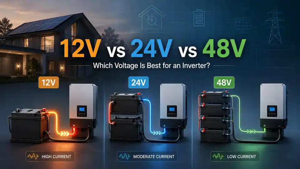
A 12 V inverter system can be compact, familiar and easy to integrate with small DC equipment. A 48 V system can deliver the same inverter power with far less battery current. Between them, 24 V is often the practical middle ground. None of these voltages is automatically the best choice for every home, cabin, vehicle, boat or workshop.
The useful question is not simply “Which voltage is more efficient?” It is: what voltage lets the complete system deliver the required power without excessive current, difficult cable runs, incompatible equipment or an expensive rebuild when the system grows?
This guide is for preliminary system planning. Battery banks can supply extremely high fault current, and a nominal 48 V battery can operate above 48 V while charging. Cable size, fuses, breakers, disconnects, battery management, earthing or grounding, transfer equipment and fixed wiring must be designed for the actual equipment and local requirements. Use qualified electrical or solar professionals for installation and final equipment selection.
Use this guide to choose the system voltage
The short answer: choose voltage from power and architecture
For a small inverter and several low-power devices, 12 V may be entirely reasonable. For a medium-size backup system, 24 V can reduce current without making every component part of a 48 V architecture. For a several-kilowatt inverter, a large solar-battery system or planned whole-home backup, 48 V is often the more sensible starting point.
A practical first shortlist
| System voltage | Often suits | Main advantage | Main question before choosing |
|---|---|---|---|
| 12 V | Small backup systems, portable setups, vehicles, boats and installations with many native 12 V loads | Simple access to 12 V equipment and batteries | Will inverter current become excessive at the planned continuous and surge power? |
| 24 V | Medium-size inverters, cabins, larger mobile systems and moderate home backup | Roughly half the current of 12 V for the same power | Are 24 V batteries, chargers, controllers and DC loads readily available for the project? |
| 48 V | Several-kilowatt inverters, larger solar systems, expandable backup and whole-home equipment | Roughly one quarter of the 12 V current for the same power | Can every battery, BMS, charger, controller, disconnect and DC load support the full operating voltage? |
There is no universal wattage at which 12 V becomes “wrong” or 48 V becomes mandatory. Product design, cable length, allowable voltage drop, battery current capability and the required surge duration can move the sensible boundary. Treat voltage as a system decision, not as a rule copied from one product chart.
Why the same inverter power creates very different battery current
An inverter converts battery DC power into AC power for appliances. Ignoring small secondary effects, the battery-side current can be estimated from the required AC power, nominal battery voltage and inverter efficiency:
Estimated DC current ≈ AC load in watts ÷ battery voltage ÷ inverter efficiency.
If voltage doubles while power and efficiency remain the same, current is approximately halved. This relationship is the main reason larger inverter systems move from 12 V to 24 V or 48 V.
Approximate battery current at 90% inverter efficiency
| AC load | 12 V system | 24 V system | 48 V system |
|---|---|---|---|
| 500 W | 46 A | 23 A | 12 A |
| 1,000 W | 93 A | 46 A | 23 A |
| 2,000 W | 185 A | 93 A | 46 A |
| 3,000 W | 278 A | 139 A | 69 A |
| 5,000 W | 463 A | 231 A | 116 A |
The inverter sees power; the battery side pays in current
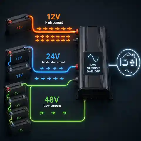
At a 3,000 W AC load and 90% efficiency, the simplified current is about 278 A from 12 V, 139 A from 24 V and 69 A from 48 V.
Actual current changes with battery voltage under load, inverter efficiency, temperature, cable loss and transient demand.
As a battery approaches its lower operating voltage, an inverter maintaining the same AC output may draw more current than the nominal-voltage estimate suggests.
Lower current can make cable routing, terminals, busbars and battery-current limits easier to manage, but it does not remove the need for correct protection.
How much current does a 3,000 W inverter load draw from 12 V, 24 V and 48 V at 90% efficiency?
Answer: 12 V: 3,000 ÷ 12 ÷ 0.90 ≈ 278 A. 24 V: ≈ 139 A. 48 V: ≈ 69 A.
Explanation: These are planning values at nominal voltage. They are not final cable, fuse, breaker, terminal or BMS ratings. Starting surges and low battery voltage can increase the required current.
Lower current changes more than cable thickness
What usually improves when current is reduced
| System issue | Why high current makes it harder | How higher voltage may help |
|---|---|---|
| Voltage drop | More current creates more voltage loss across the same cable resistance | Lower current reduces the voltage lost for the same cable and length |
| Cable heating | Resistive heating rises with the square of current | Halving current reduces I²R loss to about one quarter when resistance is unchanged |
| Cable and terminal size | Very high current demands large conductors, lugs, busbars and connection hardware | Lower current may permit more manageable components, subject to final design |
| Battery and BMS limits | A battery may contain enough energy but still be unable to provide the required amps | A higher-voltage bank can deliver the same power at lower current |
| Inverter low-voltage shutdown | Cable drop and battery voltage sag can make the inverter see a lower input voltage | Lower current can reduce part of that drop and sag |
| Expansion | Adding more inverter power to an already high-current system can require a major DC-side rebuild | Selecting a suitable voltage early can leave a more practical growth path |
Higher voltage is not a shortcut around cable design. A 48 V system can still have long cable runs, poor crimps, loose terminals, overloaded busbars or inadequate fault protection. It simply starts with less current for the same power, which can make a well-designed system easier to build.
See how current, cable length and allowable voltage drop affect conductor sizeCompare preliminary cable requirements at 12V, 24V and 48VWhat does not change: equivalent battery banks can store the same energy
Moving from 12 V to 24 V or 48 V does not create free energy. If the same four simplified 12 V 100 Ah batteries are rearranged without changing their number, their combined nominal energy remains approximately 4.8 kWh. Voltage and amp-hours change according to the wiring, but volts multiplied by amp-hours remains approximately the same.
Four 12 V 100 Ah batteries arranged three ways
| Battery-bank arrangement | Nominal bank rating | Approximate energy | What changed |
|---|---|---|---|
| All four in parallel | 12 V 400 Ah | 4,800 Wh | Amp-hour capacity adds; voltage stays at 12 V |
| Two series pairs connected in parallel | 24 V 200 Ah | 4,800 Wh | Each pair raises voltage; the two strings add capacity |
| All four in series | 48 V 100 Ah | 4,800 Wh | Voltage adds; amp-hour capacity stays at 100 Ah |
Four batteries, three voltages, the same nominal energy
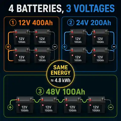
Series wiring adds battery voltage while amp-hour capacity remains the same.
Parallel wiring keeps the voltage the same while amp-hour capacity adds.
Series-parallel wiring can raise both voltage and total capacity, but equal current paths, matching batteries, protection and balancing become important.
The 4.8 kWh example uses simplified 12 V labels. Four 12.8 V 100 Ah LiFePO4 modules would contain about 5.12 kWh nominally.
Do not assume that any 12 V lithium battery may be connected in series or parallel. The internal BMS, charging method and manufacturer limits may prohibit the arrangement or limit the number of batteries. Use only configurations explicitly permitted for the exact battery model.
When a 12V inverter system makes sense
A 12 V system is often the simplest choice when loads are modest and the surrounding equipment is already built around 12 V. It is common in smaller vehicles, boats, portable systems and compact household backup arrangements. The strongest reason to stay at 12 V is usually not that 12 V is inherently better, but that many batteries, chargers and direct-DC devices are readily available in that ecosystem.
- The inverter load is relatively small and does not require extreme battery current.
- Several important loads operate directly from regulated 12 V DC.
- The installation is based on an existing 12 V alternator or vehicle electrical system.
- Cable runs between the battery and inverter can remain very short.
- The battery or BMS can supply both continuous and surge current with suitable margin.
- Future expansion is limited and unlikely to move into several-kilowatt continuous loads.
- Compatible 12 V chargers, solar controllers and protection are already part of the system.
High-power 12 V inverters exist. Their existence does not automatically make 12 V the easiest architecture for a high-power project. Check the manufacturer’s required cable arrangement, battery capacity, discharge current, fusing and installation distance before treating a large 12 V inverter as a simple upgrade.
When 24V is the useful middle ground
A 24 V bank draws roughly half the current of a 12 V bank for the same inverter output. This can make a noticeable difference without requiring every part of the project to move to 48 V. It is common in medium-size cabin, marine, vehicle and backup systems where 12 V current has become inconvenient but the load and expansion plan do not yet justify a larger 48 V architecture.
- The inverter is expected to operate in the low-to-middle kilowatt range.
- The installation has moderate cable distances or limited space for very large conductors.
- A 24 V alternator, battery, inverter/charger or existing equipment already shapes the project.
- Some 12 V loads can be supplied through a correctly selected 24-to-12 V DC-DC converter.
- The required battery bank can be built from approved 24 V batteries or a permitted series arrangement.
- The user wants lower current than 12 V without the component changes and operating voltage of a 48 V system.
When 48V becomes the sensible starting point
A 48 V battery system is often the practical choice for larger inverters, substantial solar charging, expandable battery storage and backup that supplies several circuits or a significant part of a home. The lower current is especially valuable when continuous inverter demand reaches several kilowatts or when the system may later add more power.
- The inverter will regularly supply several kilowatts rather than only brief occasional peaks.
- The project is intended to support multiple household loads or a dedicated essential-load distribution board.
- A large solar array and high charging power are planned.
- Battery modules, inverter/charger and solar equipment are available as a compatible 48 V or nominal 51.2 V system.
- Future expansion is likely and rebuilding a high-current 12 V or 24 V DC side would be costly.
- Professional design, suitable enclosure space and correctly rated protection are already part of the project.
“48 V” is a nominal class, not a promise that the battery always measures exactly 48.0 V. Lead-acid and lithium systems have different operating and charging ranges, and many LiFePO4 products marketed as 48 V are nominally 51.2 V. Every inverter, charger, controller, disconnect and protective device must be rated for the actual minimum and maximum voltage.
Choose by the real use case, not by the neatest label
Voltage tendencies for common projects
| Project | Voltage often considered first | Why | What could change the choice |
|---|---|---|---|
| Router, laptop and a few lights | 12 V | Low load and easy access to compact batteries or direct-DC equipment | Long cable runs, an existing 24 V system or planned expansion |
| Refrigerator, boiler and home-office backup | 12 V or 24 V | Power may remain moderate, but compressors and pumps need surge capability | Several appliances operating together or a large runtime requirement |
| Cabin with lighting, pump, refrigerator and small tools | 24 V | Useful balance between current and equipment complexity | A small existing 12 V installation or a future several-kilowatt solar system |
| Vehicle or boat with many native 12 V loads | 12 V, sometimes 24 V | Existing alternator and DC-load ecosystem may dominate the design | Large inverter loads may justify a separate or converted higher-voltage house system |
| Several-kilowatt household backup | 48 V | Lower current makes the battery-to-inverter side more manageable | A smaller, strictly limited essential-load design may work at 24 V |
| Expandable solar-plus-storage system | 48 V | Common architecture for larger charging power and inverter capacity | Product ecosystem, local support and approved battery compatibility |
The table is a starting point rather than a product-selection rule. A carefully designed 12 V system can be more appropriate than a poorly matched 48 V one. The final choice comes from the actual load profile, available hardware, cable route, charging source and permitted battery configuration.
Six parts of the system must agree on voltage
Changing voltage changes the complete equipment list
| Component | What voltage affects | What to confirm |
|---|---|---|
| Inverter or inverter/charger | DC input range, low-voltage shutdown, charging voltage and current | The exact model is built for the selected battery-voltage class |
| Battery and BMS | Nominal voltage, series permissions, discharge current and communication | Continuous and peak current, operating range and approved configuration |
| AC charger | Charging profile and output voltage | Battery chemistry, bank voltage, charge current and temperature requirements |
| Solar charge controller | Permitted battery voltage and output current | Battery-voltage support, PV input limits and maximum charging power |
| DC appliances | Whether they can connect directly to the bank | Use a properly rated DC-DC converter when load voltage differs |
| Fuses, breakers, switches, contactors and monitors | Voltage rating, current rating, interruption capability and measurement range | Every device is DC-rated for the maximum system voltage and prospective fault current |
A 12 V inverter cannot be upgraded to a 24 V or 48 V battery bank by changing a setting unless the manufacturer explicitly designed that model for multiple input voltages. Connecting the wrong battery voltage can destroy equipment and create a serious hazard.
Series, parallel and series-parallel without the usual confusion
Battery-bank voltage is often created by combining smaller batteries, but the wiring arrangement changes how the bank behaves. Series raises voltage. Parallel raises amp-hour capacity and current capability. Series-parallel does both and also introduces more paths that must share current correctly.
What each connection changes
| Connection | Voltage | Amp-hours | Important design issue |
|---|---|---|---|
| Series | Adds | Stays equal to one battery | Battery matching, balance and the permitted BMS series voltage |
| Parallel | Stays equal to one battery | Adds | Equal current paths, individual-string protection and current sharing |
| Series-parallel | Adds by series count | Adds by parallel-string count | String matching, busbars, fusing, balance and fault isolation |
- Use batteries of the same model, chemistry, capacity and compatible age unless the manufacturer states otherwise.
- Fully charge and balance batteries as required before creating a series bank.
- Follow the battery manufacturer’s exact limit for series and parallel units.
- Use busbars or another approved arrangement that gives parallel batteries or strings equal current paths.
- Protect individual batteries or strings where required and protect the main bank connection.
- Do not attach a lower-voltage load to the midpoint of a series bank.
- Monitor individual modules or string midpoints where the battery system requires it.
Do not take 12 V from one battery in a 24 V or 48 V series bank. That battery will be discharged differently from the others and the bank can become severely unbalanced. Use a correctly selected DC-DC converter connected across the full bank.
Worked example: the same 2kW backup load at three voltages
Consider an essential-load system supplying up to 2,000 W continuously through an inverter operating at an assumed 90% efficiency. The load and required AC output are identical. Only the nominal battery voltage changes.
What is the estimated DC current for a 2,000 W load?
Answer: At 12 V: about 185 A. At 24 V: about 93 A. At 48 V: about 46 A.
Explanation: The calculation is 2,000 ÷ voltage ÷ 0.90. Actual current may be higher at low battery voltage and during surge events.
How does doubling voltage change cable loss if total circuit resistance stays at 0.002 ohm?
Answer: Approximate I²R loss is 69 W at 12 V, 17 W at 24 V and 4 W at 48 V.
Explanation: This is an illustration, not a cable design. When current halves, resistive loss falls to about one quarter for the same resistance. Real cable resistance depends on conductor material, cross-sectional area, total path length, temperature, terminals and connection quality.
What the 2kW comparison means in practice
| Design question | 12 V | 24 V | 48 V |
|---|---|---|---|
| Approximate continuous current | 185 A | 93 A | 46 A |
| Battery discharge requirement | Very demanding for one small battery or BMS | Moderate-to-high depending on bank design | Lower current for the same power |
| Effect of a long DC cable run | Can become difficult quickly | More manageable | Usually easiest of the three |
| Direct 12 V loads | Can use the bank when voltage range is compatible | Need a converter or separate supply | Need a converter or separate supply |
| Future move to 4 kW | Likely requires a major current-side review | May still be practical with suitable equipment | Usually offers the clearest growth path |
The battery must satisfy both energy and power. A bank may store enough watt-hours for the required runtime but still fail because one module or its BMS cannot supply the inverter’s continuous or surge current. Check battery current limits at the lowest expected operating voltage, not only at the nominal label voltage.
How system voltage affects charging and solar equipment
Charging power follows the same basic relationship. A simplified 1,200 W charge into a battery bank corresponds to about 100 A at 12 V, 50 A at 24 V or 25 A at 48 V before allowing for the actual charging voltage and conversion losses. Higher battery voltage can therefore make high charging power easier to deliver within controller and cable current limits.
Simplified current for 1,200 W of battery charging
| Nominal battery voltage | Idealised current | What still has to be checked |
|---|---|---|
| 12 V | 100 A | Actual charge voltage, controller current limit, cable size and battery charge limit |
| 24 V | 50 A | Controller support for 24 V, charging profile and maximum output power |
| 48 V | 25 A | Controller support for the full battery range, communication and battery maximum voltage |
Solar-array voltage and battery-bank voltage are not the same design value. An MPPT controller may accept a much higher PV input voltage and convert it to the battery charging voltage. The array configuration must remain within the controller’s minimum, maximum, cold-weather open-circuit and current limits.
Plan the second version of the system before buying the first
Many systems begin with a refrigerator, router and several lights, then add a pump, larger inverter, solar charging, workshop tool or essential household circuit. A voltage that is comfortable for the first 600 W may become awkward when the real plan reaches 3,000 W.
Questions that reveal the likely future system
| Question | Why it changes the voltage decision |
|---|---|
| Will another inverter or a larger inverter be added? | Future continuous power may make today’s current and cable architecture unsuitable |
| Will battery capacity grow by adding modules? | The permitted parallel count, communication and busbar design may limit expansion |
| Will solar charging increase? | Controller output current and maximum charging power may favour a higher battery voltage |
| Will the system supply fixed household circuits? | Transfer equipment, protection and professional installation become part of the design |
| Will important 12 V loads remain? | A higher-voltage bank may require one or more DC-DC converters |
| Are replacement parts and technical support available locally? | A theoretically ideal voltage is less useful when compatible equipment cannot be serviced or replaced |
Oversizing every component “just in case” can waste money and increase inverter idle consumption. The better approach is to define a credible expansion stage, then choose a voltage and equipment family that can reach it without rebuilding the entire DC side.
A practical seven-step selection method
- List the appliances that may genuinely operate together and identify their continuous and startup power.
- Choose the maximum credible inverter size for the current project and one realistic future expansion stage.
- Calculate approximate battery current at 12 V, 24 V and 48 V using the inverter efficiency expected at that load.
- Review cable length, routing, voltage drop, connection space and the current ratings of terminals, busbars and protection.
- Check whether suitable batteries, BMS, inverter/charger, solar controller and DC-DC converters are available as one compatible voltage family.
- Confirm that the battery bank can supply continuous and surge current and that its permitted series or parallel configuration creates the required voltage.
- Have the final design checked for cables, protection, fault current, isolation, earthing or grounding, transfer equipment, ventilation and local compliance.
Common voltage-selection mistakes
Mistake, consequence and better approach
| Mistake | What can go wrong | Better approach |
|---|---|---|
| Choosing voltage from one appliance | The rest of the system may create much higher simultaneous load | Model the busiest credible group of loads and startup events |
| Comparing batteries only by Ah | A 12 V 100 Ah battery is mistaken for the same energy as a 48 V 100 Ah bank | Compare nominal and usable watt-hours as well as current capability |
| Buying the inverter before choosing the battery architecture | The available battery, BMS or charger may not match its DC input | Select the voltage family and compatible components together |
| Assuming higher voltage automatically means longer runtime | The same stored watt-hours provide similar theoretical energy regardless of arrangement | Calculate usable Wh, inverter loss and real load |
| Using one battery from a series bank for 12 V loads | The series bank becomes unbalanced | Use a correctly rated DC-DC converter across the full bank |
| Ignoring inverter idle consumption | A large inverter wastes a noticeable share of energy on small loads | Check no-load and low-load consumption as well as peak efficiency |
| Assuming every lithium battery can be placed in series | The BMS may be damaged or disconnect unpredictably | Follow the exact battery manufacturer’s approved configurations |
| Treating nominal current as the final design current | Surge, low battery voltage and temperature may exceed the estimate | Check worst-case operating and fault conditions professionally |
Safety matters at every one of these voltages
Do not describe a battery bank as harmless because it is “only 12 V” or “only 48 V”. Even low-voltage batteries can deliver enough fault current to melt tools, start fires, destroy terminals or cause severe burns. At higher nominal voltages, shock, arcing and equipment-isolation concerns also become more significant.
- Use over-current protection located and rated according to the equipment design and battery manufacturer instructions.
- Use DC-rated fuses, breakers, disconnects and contactors with adequate voltage and interruption ratings.
- Keep battery-to-inverter cables short where practical and protect them from movement, abrasion and accidental contact.
- Use correctly crimped lugs, suitable terminals, insulated tools and specified tightening torque.
- Protect each parallel battery or series string when the design or manufacturer requires it.
- Do not work on an energised bank or place tools and jewellery where they can bridge terminals.
- Provide the ventilation, temperature control, clearances and enclosure required by the battery and inverter.
- Do not connect a portable inverter to household wiring through a socket or improvised backfeed lead.
- Use professionally designed transfer, earthing or grounding, bonding and protective arrangements for fixed installations.
Professional design is especially important for several-kilowatt inverters, permanent household circuits, multiple parallel strings, large lithium banks, generator integration, automatic transfer, unusual earthing or grounding arrangements, and any project where the expected fault current or protection method is uncertain.
Technical references used for this guide
The references below illustrate the main design principles: increasing battery-system voltage reduces current for a given power; parallel paths must share current correctly; series banks require attention to balance; lower-voltage loads should not be connected to a midpoint; and battery manufacturers place model-specific limits on series, parallel and BMS configurations.
Victron Energy Wiring Unlimited: DC current, voltage drop, cable selection and system voltageVictron Energy Wiring Unlimited: parallel battery paths, series balance and midpoint loadsVictron Lithium Battery Smart manual: manufacturer-specific series, parallel and protection requirementsDiscover Battery: why lithium battery voltage and BMS architecture must match the applicationMastervolt DC Master: examples of DC-DC conversion between 12V, 24V and 48V systemsFrequently asked questions
Is a 48V inverter system more efficient than 12V?
It can reduce battery-side current and therefore reduce cable voltage drop and resistive loss for the same conductor resistance. Total system efficiency still depends on the actual inverter, battery, cables, operating load, DC-DC converters and charging equipment. A well-designed 12 V system may outperform a poorly designed 48 V one at a small load.
Can I run a 2,000W inverter from a 12V battery?
Yes, when the inverter, battery bank, BMS, cables, terminals and protection are designed for the required current and surge. At 2,000 W and 90% efficiency, the simplified current is about 185 A at 12 V, and it may be higher at low battery voltage. This is not a modest demand for one small battery.
Should a 3,000W inverter use 24V or 48V?
Both architectures can be technically possible. At 90% efficiency, the simplified current is about 139 A at 24 V and 69 A at 48 V. Cable route, battery current limits, charging equipment, future expansion and the available inverter family often make 48 V more attractive, but the complete product specifications decide the result.
Does a higher battery voltage increase runtime?
Not by itself. Runtime depends mainly on usable battery energy in watt-hours and the real load. A 12 V 400 Ah bank, 24 V 200 Ah bank and 48 V 100 Ah bank each store about 4.8 kWh nominally. Higher voltage may reduce cable losses, but it does not multiply the stored energy.
Can I rewire four 12V batteries into a 48V bank?
Only when the exact batteries are approved for series connection and the inverter, charger, controller, protection and monitoring all support the resulting operating voltage. The batteries should be matched and prepared according to the manufacturer’s procedure. Some drop-in lithium batteries must not be placed in series.
Is a 51.2V LiFePO4 battery a 48V battery?
It is commonly sold within the 48 V nominal system class. The actual battery voltage changes with state of charge and charging conditions. Confirm that the inverter and charger support the battery manufacturer’s full operating range and any required BMS communication.
Can I power 12V devices from a 24V or 48V battery bank?
Yes, through a correctly selected and protected DC-DC converter with suitable input-voltage range, output current and isolation where required. Do not connect the load to one battery or a midpoint in a series bank.
Is 24V always the best compromise?
No. It is a useful middle ground for many medium-size systems, but a small 12 V installation may be simpler and a planned several-kilowatt or expandable system may be better started at 48 V. The compromise is valuable only when compatible equipment and the expected growth path support it.
Choose the voltage once, then build the system around it
The best inverter-system voltage is the one that supports the real continuous load, startup demand, cable route, battery current, charging sources, DC appliances and future expansion without forcing awkward compromises. Use 12 V where the system is genuinely small and benefits from a 12 V ecosystem. Use 24 V when it provides a practical reduction in current for a medium-size project. Start with 48 V when several-kilowatt power, substantial solar charging or expandable home backup is already part of the plan.
After choosing the voltage, verify every component as part of the same architecture. The inverter label is only one piece. A dependable system also needs a battery and BMS that can supply the current, compatible charging equipment, correctly designed DC wiring and protection, and an installation that handles faults and source transfer safely.
Calculate inverter load, surge requirement and battery current