
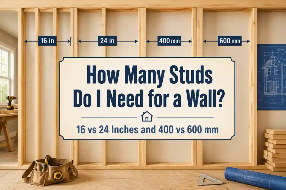
To estimate the number of studs in a straight wall, divide the wall length by the planned on-center or on-centre spacing, round the number of spaces up, and add one stud for the far end. That gives the baseline full-height layout for an uninterrupted wall. A complete framing order usually needs more material for doors, windows, corners, intersecting walls, jack or trimmer studs, cripple studs, plates, blocking and cutting allowance.
The familiar choices of 16 or 24 inches on center and 400 or 600 mm centres are layout modules, not universal permissions. The permitted spacing depends on whether the wall is load-bearing, its height, stud size and grade, wind and seismic loads, sheathing, cladding, plasterboard or drywall, fire and acoustic requirements, and the building rules that apply where the project is located.
Quick answer: baseline studs = round wall length ÷ spacing up to the next whole space, then add 1. A 12 ft wall needs 10 baseline studs at 16 in o.c. or 7 at 24 in o.c. A 4.8 m wall needs 13 baseline studs at 400 mm centres or 9 at 600 mm centres.
This guide estimates quantities; it does not approve a stud size or spacing. Do not widen the spacing merely to reduce the material count. Use the approved drawings, local code and the instructions for the complete wall assembly.
Which Stud Count Do You Actually Need?
The question “How many studs do I need?” can refer to several different numbers. The regular layout count is useful for understanding the wall, but it is not always the number of timber or lumber pieces that should be purchased.
Four different framing quantities
| Quantity | What it includes | What it is used for |
|---|---|---|
| Baseline stud positions | Regular full-height positions for a straight wall with no openings | Checking the basic spacing layout |
| Full-height studs in the frame | Regular positions that remain after openings, plus king studs and extra corner or intersection studs | Counting complete wall-height members |
| Vertical framing pieces | Full-height studs, jack or trimmer studs and cripple studs | Understanding every vertical piece in the finished frame |
| Stud stock pieces to buy | Complete boards needed after stock length, offcut reuse and waste are considered | Preparing the actual shopping order |
For purchasing, do not stop at the baseline stud count. The useful shopping result is the number of complete stock pieces needed for the entire framing layout.
Plan the wall framing
The Basic Stud Count Formula
For one straight wall with a stud at both ends and no openings, use three simple steps. Divide the wall length by the selected stud spacing, round the number of spaces up to the next whole number, and then add one stud for the opposite end of the wall. In short: baseline studs = round up (wall length ÷ stud spacing) + 1. This gives the regular full-height layout only. Doors, windows, corners, wall intersections and other additional framing are counted separately.
What each part of the formula means
| Part | Meaning | Practical effect |
|---|---|---|
| Wall length | The full framed length from one end of the wall to the other | Use the actual wall dimension, not the floor area |
| Stud spacing | The distance from the centre of one regular stud to the centre of the next | Use the spacing shown on the approved plan |
| Round spaces up | A partial final bay still requires another stud position | Prevents the last spacing from becoming wider than planned |
| Add one | Spaces occur between studs | Nine spaces require ten studs |
| Additional framing | Openings, corners, intersections and special supports | Added after the uninterrupted baseline is understood |
How many studs are in a 12 ft wall at 16 inches on center?
Answer: The uninterrupted baseline is 10 studs, including both wall ends.
Explanation: Twelve feet equals 144 inches. Dividing 144 by 16 gives 9 spaces. Nine spaces need 10 stud positions. Add opening framing, corners, intersections and purchase allowance separately.
How many studs are in a 4.8 m wall at 600 mm centres?
Answer: The uninterrupted baseline is 9 studs, including both ends.
Explanation: The wall is 4,800 mm long. Dividing 4,800 by 600 gives 8 spaces. Eight spaces require 9 studs.
Why Both Wall Ends Are Counted
Calculate Each Wall Separately
For a room, extension or complete floor plan, calculate each straight wall run separately rather than entering the total room perimeter as one long wall. Stud spacing normally restarts from the reference end of each wall, and every corner, intersection, door and window belongs to a specific wall layout.
Can I enter the 44 ft perimeter of a 12 × 10 ft room as one wall?
Answer: No. Calculate the two 12 ft walls and the two 10 ft walls separately, then add the approved corner and intersection framing.
Explanation: Treating the whole perimeter as one uninterrupted wall hides the wall ends, resets in stud layout, corner details and the exact positions of openings. The combined linear length may be correct, but the framing count may not be.
Count each wall once, then add only the extra corner members required by the selected detail. Otherwise, a very enthusiastic corner can appear in both wall totals.
What On Center or On Centre Actually Means
Measure from centre line to centre line
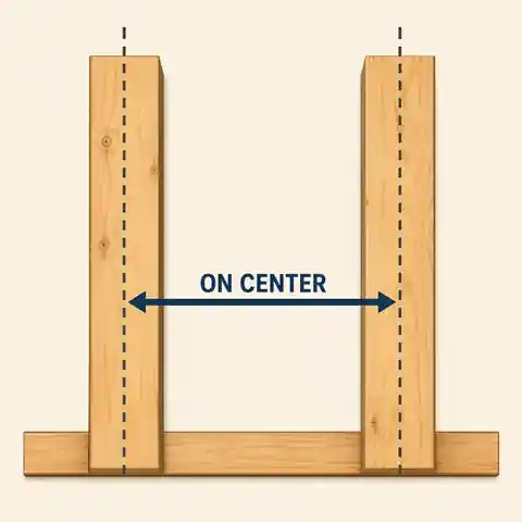
A spacing of 16 in o.c. means 16 inches from the centre line of one stud to the centre line of the next, not a 16-inch clear gap.
With a typical actual stud thickness of 1.5 inches, the clear space between two regularly placed studs is about 14.5 inches.
The same principle applies in metric framing: 600 mm centres describes the module between centre lines, while the clear cavity is smaller by one stud thickness.
- Mark the first reference edge according to the framing plan and lining layout.
- Keep the same face of the tape measure as the reference throughout the wall.
- Mark both the stud edge and an X on the side where the stud will sit.
- Check that sheet edges, openings and intersections are supported as required.
- Do not assume a clear cavity width is the same number as the on-centre spacing.
When laying out a wall, mark the stud side as well as the centre. A lonely pencil line can become surprisingly persuasive after lunch.
16 vs 24 Inches on Center
Spacing studs at 24 inches rather than 16 inches reduces the number of regular stud positions on a long uninterrupted wall by roughly one third. It can also create wider insulation cavities and less repeated timber through the wall. Those advantages apply only when the structure, sheathing, lining, cladding, fasteners and load path are designed for the wider module.
Planning comparison: 16 in and 24 in on center
| Detail | 16 in o.c. | 24 in o.c. |
|---|---|---|
| Exact spacing | 16 in (406.4 mm) | 24 in (609.6 mm) |
| Regular studs on a 12 ft wall | 10 baseline studs | 7 baseline studs |
| Regular studs on a 16 ft wall | 13 baseline studs | 9 baseline studs |
| Four-foot sheet module | Three 16-inch spaces across 48 in | Two 24-inch spaces across 48 in |
| Material use | More regular studs | Fewer regular studs when the assembly permits it |
| Cavity width | Narrower cavities | Wider cavities |
| Design sensitivity | Still depends on the complete wall design | Often needs more deliberate alignment and assembly checks |
Baseline studs for common wall lengths
| Wall length | 16 in o.c. | 24 in o.c. | Difference |
|---|---|---|---|
| 8 ft | 7 | 5 | 2 fewer at 24 in |
| 10 ft | 9 | 6 | 3 fewer at 24 in |
| 12 ft | 10 | 7 | 3 fewer at 24 in |
| 14 ft | 12 | 8 | 4 fewer at 24 in |
| 16 ft | 13 | 9 | 4 fewer at 24 in |
| 20 ft | 16 | 11 | 5 fewer at 24 in |
The table counts regular full-height positions for a straight uninterrupted wall. It does not include doors, windows, corner packs, partition intersections, hold-down details or any project allowance.
400 vs 600 mm Centres
Metric wall systems often use modules such as 400, 450 or 600 mm. Both 400 and 600 mm divide a 1,200 mm board width evenly: three 400 mm spaces or two 600 mm spaces. In Australia, many proprietary systems are designed around 450 or 600 mm centres, while some tested UK timber partition systems permit a maximum of 600 mm centres. These are system-specific limits. The stud dimensions, wall height, loads, boards, insulation, fixings and required performance must still match the selected specification.
Planning comparison: 400 and 600 mm centres
| Detail | 400 mm centres | 600 mm centres |
|---|---|---|
| Module across a 1,200 mm board | Three spaces | Two spaces |
| Baseline studs on a 3.6 m wall | 10 | 7 |
| Baseline studs on a 4.8 m wall | 13 | 9 |
| Baseline studs on a 6.0 m wall | 16 | 11 |
| Regular framing density | More studs per metre | Fewer studs per metre where approved |
| Compatibility check | Board, insulation and assembly requirements | Board span, wall height, loads, bracing and lining requirements |
Baseline metric stud counts
| Wall length | 400 mm centres | 600 mm centres | Difference |
|---|---|---|---|
| 2.4 m | 7 | 5 | 2 fewer at 600 mm |
| 3.0 m | 9 | 6 | 3 fewer at 600 mm |
| 3.6 m | 10 | 7 | 3 fewer at 600 mm |
| 4.0 m | 11 | 8 | 3 fewer at 600 mm |
| 4.8 m | 13 | 9 | 4 fewer at 600 mm |
| 6.0 m | 16 | 11 | 5 fewer at 600 mm |
Do not silently substitute 400 mm for 16 inches or 600 mm for 24 inches. Sixteen inches is 406.4 mm and 24 inches is 609.6 mm. They are related layout families, not exact conversions.
Four useful modules, not four interchangeable approvals
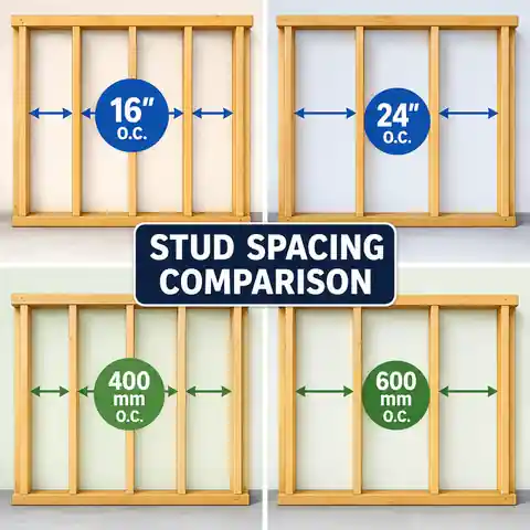
A 4 ft sheet aligns naturally with both 16 and 24 inch modules, while a 1,200 mm sheet aligns with both 400 and 600 mm modules.
The final bay may be shorter when the wall length is not an exact multiple of the selected spacing.
Openings interrupt the regular module and require their own framing members.
The wider option is not automatically suitable for every wall covering, load or tested assembly.
Does 2×4 vs 2×6 Change the Number of Studs?
Stud depth does not change the basic count by itself. If two walls have the same length, the same on-center spacing and the same openings, a 2×4 wall and a 2×6 wall normally have the same baseline stud positions. The deeper stud changes the wall thickness, structural capacity, insulation space, weight and material cost, but not the spacing arithmetic.
What changes when the stud size changes
| Detail | Does stud size affect it? | Planning note |
|---|---|---|
| Baseline stud count | Not by itself | The count comes from wall length and approved spacing |
| Wall depth | Yes | A deeper stud creates a thicker wall cavity |
| Structural capacity | Yes | Stud size, grade, height, spacing and supported loads work together |
| Insulation space | Yes | A deeper cavity can accept a different insulation thickness |
| Material cost and weight | Yes | Larger members normally use more material |
| Permitted spacing | Possibly | The approved spacing may change with stud size and wall design |
Use the actual supplied dimensions in the calculator. A nominal product name such as 2×4 or 2×6 is not the same as the finished dimensions of the timber.
Doors and Windows Change the Real Count
A door or window is not handled by subtracting its width from the wall and continuing with the basic formula. The opening removes some regular stud positions but adds full-height and short framing members around the rough opening. Its exact location matters because an opening can replace a different number of regular positions depending on where it falls within the layout module.
The members around a rough opening
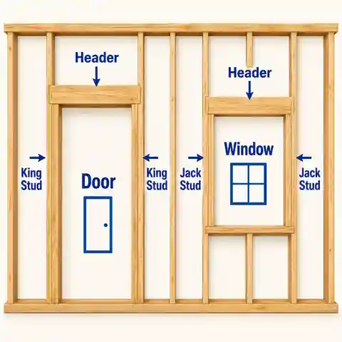
King studs commonly run full height beside the opening.
Jack or trimmer studs support the header or lintel where the design requires them.
Cripple studs can continue the regular module above the header and below a window sill.
A window also needs sill members and short studs below the sill.
Header or lintel dimensions and bearing cannot be selected from a generic stud-count formula.
Framing members that may be added around openings
| Member | Also called | Quantity effect |
|---|---|---|
| King stud | Full-height opening stud | Usually added at one or both sides according to the detail |
| Jack stud | Trimmer stud | Supports the header or lintel and is shorter than a full-height stud |
| Header | Lintel | Separate horizontal member sized for the actual wall and load |
| Upper cripple stud | Short stud above the header | Often follows the regular wall module |
| Sill | Window sill framing | Horizontal member below a window rough opening |
| Lower cripple stud | Short stud below a window | Supports the sill and lining module |
| Additional bearing stud | Extra jack or trimmer | May be required for wider or more heavily loaded openings |
The number of king studs, jack studs and header plies is not universal. Opening width, supported loads, material, wall type and local requirements control the detail.
Can I subtract a 3 ft door from a 12 ft wall and calculate studs for the remaining 9 ft?
Answer: No. That method ignores the exact location of the opening and the studs, header supports and short members added around it.
Explanation: A door may remove regular positions inside the rough opening, but it normally adds framing at both jambs. Enter the rough opening position and size into a framing calculator or count the approved opening detail member by member.
Top and Bottom Plates Are a Separate Quantity
Stud count describes vertical members. Plates are horizontal boards running along the wall. A common preliminary arrangement may have one bottom or sole plate and one or two top plates, but the required number and splice locations depend on the wall design and construction method.
Preliminary plate calculation
| Plate arrangement | Total linear plate length | Before ordering |
|---|---|---|
| One bottom + one top | Wall length × 2 | Check whether a double top plate is required |
| One bottom + double top | Wall length × 3 | Allow for approved lap and splice details |
| Two bottom + double top | Wall length × 4 | Use only where the designed assembly calls for it |
| Open doorway | Do not automatically deduct from every plate layer | The bottom plate may be installed continuously and cut later |
How much plate length is needed for a 12 ft wall with one bottom plate and a double top plate?
Answer: The geometric total is 36 linear feet before stock-board rounding, laps, splices and waste.
Explanation: There are three plate layers: 12 ft × 3 = 36 ft. If only 8 ft boards are available, the purchase is based on complete boards and approved splice placement, not simply 36 ÷ 8 rounded without a layout check.
Corners and Intersecting Walls Need Their Own Detail
The baseline count includes one regular stud at each wall end, but it does not decide how corners or partition intersections are built. Conventional multi-stud corners, two-stud insulated corners, ladder blocking, California corners and proprietary connectors use different quantities and provide different fixing surfaces.
Details that can add full-height studs
| Location | Possible framing approach | Counting method |
|---|---|---|
| External corner | Two-stud, three-stud or another approved corner | Add only the studs beyond the regular end position |
| Internal corner | Backing stud, ladder blocking or clips | Count the actual approved support detail |
| Partition intersection | Extra stud pack or backing between regular positions | Add the members shown on the framing plan |
| Cabinet or fixture support | Blocking or additional studs | Count separately from regular spacing |
| Shear or braced wall end | Hold-down and boundary framing detail | Use the structural drawings |
Count the baseline wall once, then add only the extra members required by each junction. Counting every corner pack in full can accidentally count the end stud twice.
Blocking, Noggings and Backing Are Not Regular Studs
Blocking or noggings are horizontal or short members between studs. They may support board joints, improve restraint, provide fixing for cabinets or handrails, form fire or cavity barriers, or satisfy a tested wall system. Their quantity is normally calculated by rows and stud bays rather than added as full-height studs.
Ways blocking can be estimated
| Requirement | Useful preliminary method | What can change it |
|---|---|---|
| One continuous row | Approximately one block per clear stud bay | Openings, corners and staggered installation |
| Support for a horizontal board joint | Measure only the joint locations needing support | Board orientation and approved lining system |
| Cabinet or handrail backing | Measure the actual supported zone | Fixture loads and fixing detail |
| Fire blocking or cavity barrier | Follow the required locations exactly | Building type, cavity geometry and local rules |
| Window sill and header zone | Count opening-specific short members | Opening width, framing detail and regular module |
Do not use a generic row of noggings as a substitute for structural bracing, a fire-stopping detail or an approved wall assembly.
Overall Wall Height Is Not the Stud Cut Length
The full-height stud fits between the bottom and top plates. Its preliminary cut length equals the overall framed wall height minus the combined actual thickness of every top and bottom plate layer. Nominal lumber names should not be used as actual thicknesses unless they match the supplied product.
What is the stud cut length for an 8 ft overall wall with one 1.5 in bottom plate and two 1.5 in top plates?
Answer: The preliminary cut length is 91.5 inches, or 7 ft 7.5 in.
Explanation: Eight feet equals 96 inches. Three plate layers total 4.5 inches. Therefore, 96 − 4.5 = 91.5 inches. Verify the actual plate thickness and framing detail before cutting the full batch.
What is the stud cut length for a 2.4 m overall wall with three 38 mm plate layers?
Answer: The preliminary cut length is 2,286 mm.
Explanation: The plate layers total 114 mm. Subtracting 114 mm from the 2,400 mm overall height gives 2,286 mm.
Cut one test stud and check the assembled height before turning the saw into a very efficient producer of identical mistakes.
Stock Lengths Decide How Many Pieces to Buy
A linear-foot or linear-metre total does not automatically become a purchase quantity. Full-height studs normally require individual stock pieces long enough to produce them without splicing. Plates may be assembled from several boards, while short jack studs, cripple studs and blocks may use suitable offcuts if the framing plan and material quality allow it.
How stock length changes the order
| Material group | Purchase logic | Common mistake |
|---|---|---|
| Full-height studs | One sufficiently long stock piece for each full-height member | Dividing total stud length by stock length and assuming studs can be spliced |
| Top and bottom plates | Complete boards arranged with approved splice positions | Ignoring that the calculated fraction must become a buildable layout |
| Jack and cripple studs | Short pieces may come from verified reusable offcuts | Assuming every offcut is the correct length and grade |
| Blocking and backing | Count pieces or total length by location | Buying no reserve for knots, splits and unusable ends |
| Headers or lintels | Separate product and stock calculation | Pricing them as ordinary studs without a specified section |
How Much Extra Framing Lumber or Timber Should You Allow?
An allowance covers damaged pieces, unusable ends, defects, cutting errors and uncertainty in short-member reuse. It should be applied after the framing layout is understood. A percentage cannot repair a missing opening, an incorrect stud height or an uncounted corner.
Illustrative purchase allowances
| Project condition | Possible planning approach | Before increasing the percentage |
|---|---|---|
| Simple straight partition with a clear cutting list | Small allowance or one verified spare piece | Check stock straightness, return policy and delivery reliability |
| Typical wall with one or two openings | Moderate controlled allowance | Count every opening member first |
| Several openings, corners and short pieces | Use a cutting list and a larger practical reserve | Identify which offcuts can serve named locations |
| First-time DIY framing | Include additional tolerance for cutting and selection | Do not use extra material as permission to skip the layout |
| Remote delivery or limited matching stock | Prioritise enough complete suitable pieces | Confirm storage, protection and return conditions |
| Structural or treated timber with strict specification | Order by the approved schedule and supplier units | Do not replace grade, treatment or section with a generic spare |
Round each material group separately. Ten full-height studs, three plate boards and several short pieces are not one interchangeable pile merely because they are all made of wood.
Stud Spacing and Sheet Layout Must Agree
Common spacing modules coordinate with standard sheet widths, but board compatibility depends on more than the edge landing on a stud. Board thickness, orientation, supported edges, fastener spacing, wall height, impact demand, tile loads and fire or acoustic system requirements can all require closer supports or additional framing.
Sheet coordination examples
| Sheet or board width | Compatible mathematical modules | What still needs verification |
|---|---|---|
| 48 in | 16 in and 24 in divide the width evenly | Board type, thickness, orientation, edge support and fasteners |
| 1,200 mm | 400 mm and 600 mm divide the width evenly | Selected lining system and permitted stud spacing |
| 1,350 mm | Often coordinates with 450 mm modules | Regional product and wall-system instructions |
| Non-standard panel | May not align with the chosen module | Create a panel layout before framing |
| Tile backer or heavy finish | May require closer support or extra backing | Product data and load requirements |
A board fitting the module does not prove that the wall assembly is approved. Tested fire, acoustic, moisture-resistant and impact-resistant systems must be built with their specified components and spacing.
When 24 Inches or 600 mm Is Not Your Choice
In the United States, the IRC does not provide a blanket rule that every wall may use either 16 or 24 inch spacing. Permitted stud size, height and spacing depend on the wall type, lumber grade and supported loads. A 24 inch advanced-framing wall is also more than a wider tape-measure layout: systems described by APA coordinate 2×6 studs, structural panel sheathing, aligned framing members and a direct load path.
In Canada, the National Building Code is a model code that provinces and territories may adopt with local changes. Its framing provisions use metric member sizes and spacing, but the applicable provincial or territorial code must be checked for the actual project. In the United Kingdom and Australia, proprietary and tested wall systems similarly specify the complete assembly rather than approving 600 mm centres as an isolated number.
Regional terminology and common modules
| Market | Wording commonly encountered | Important planning note |
|---|---|---|
| United States | 16 or 24 inches on center; studs, bottom plate, top plate | Use the adopted local code and approved wall design |
| Canada | Metric spacing such as 400 or 600 mm in code tables; imperial wording may also appear in trade use | Check the building code adopted by the relevant province or territory |
| United Kingdom | 400 or 600 mm centres; timber studs, sole plate, head plate, noggings | Follow the specified partition or structural system |
| Australia | 450 or 600 mm centres appear in many proprietary timber wall systems | Check NCC requirements, applicable timber-framing standards, wind conditions and the selected lining or cladding system |
| Any market | Custom or engineered spacing | Use the structural and assembly documentation without substituting a nearby standard module |
Do not frame a load-bearing, braced, shear, fire-rated, acoustic or external wall from a quantity article alone. A qualified designer, applicable code and the selected system documentation must establish the wall construction.
Technical References Used for This Guide
The references below illustrate why stud spacing must be checked as part of a complete wall system. They are not interchangeable specifications, and local adoption, amendments and current product literature must be verified for the project.
2024 International Residential Code: stud size, height and spacing2024 International Residential Code: bearing studs and alignment conditionsNational Building Code of Canada: official publication and provincial or territorial adoption contextBritish Gypsum timber stud partition example at 600 mm centresJames Hardie Australia design guide showing spacing, stud size, height and load conditionsGyprock Red Book: Australian wall and ceiling system guidanceA Complete Measuring and Ordering Workflow
- Confirm whether the wall is load-bearing, braced, external, fire-rated, acoustic or a simple non-load-bearing partition.
- Obtain the approved stud size, grade and on-centre spacing.
- Measure the full wall length and overall framed height.
- Mark every door, window and custom opening by position, rough width, rough height and sill height where applicable.
- Calculate the uninterrupted baseline stud positions.
- Remove only the regular positions actually interrupted by each opening.
- Add the approved king studs, jack or trimmer studs, cripple studs, sills and header or lintel pieces.
- Add extra members for corners, intersecting walls, hold-downs, fixtures and backing.
- Calculate every top and bottom plate layer using real stock lengths and approved splice locations.
- Calculate blocking or noggings by actual row and bay rather than as full-height studs.
- Check full-height stud cut length against the stock lengths available.
- Create a simple cutting list for short members and identify realistic offcut reuse.
- Add a controlled purchase allowance and round each material group to complete sale units.
- Verify the final framing plan against sheathing, drywall or plasterboard, insulation, cladding and fixture layouts.
- Keep the structural and system specification with the material list so the quantity cannot be separated from its assumptions.
Worked Example: 12 ft Wall at 16 Inches on Center
Consider a straight 12 ft wall with an overall framed height of 8 ft, 16 in spacing, actual 1.5 in plate thickness, one bottom plate, a double top plate and no openings. This example isolates the baseline geometry before corners or project allowance.
Imperial example inputs and results
| Item | Calculation | Result |
|---|---|---|
| Baseline stud positions | 144 in ÷ 16 in = 9 spaces; add 1 | 10 studs |
| Stud cut length | 96 in − (3 × 1.5 in) | 91.5 in |
| Total plate length | 12 ft × 3 layers | 36 linear ft |
| Plate boards with 8 ft stock | 36 ft total ÷ 8 ft per board = 4.5 | 5 boards is the mathematical minimum; verify whether the approved splice layout permits the required offcut reuse |
| Opening framing | No openings in this example | 0 additional opening members |
| Corner and intersection extras | Depends on how this wall connects | Add from the framing detail |
Five 8 ft boards provide 40 linear ft for the 36 ft of plate material in this example. That minimum works only when the required 4 ft sections can be cut and reused in suitable splice locations. Six boards may still be appropriate when splice requirements, defects, cutting loss or the planned assembly prevent efficient sharing of offcuts.
Worked Example: 4.8 m Wall at 400 and 600 mm Centres
Now compare a 4.8 m uninterrupted wall at two metric modules. The overall framed height is 2.4 m, plate thickness is 38 mm, and the wall has one bottom plate plus two top plates.
Metric example comparison
| Item | 400 mm centres | 600 mm centres |
|---|---|---|
| Spaces along 4,800 mm | 12 | 8 |
| Baseline full-height studs | 13 | 9 |
| Stud cut length | 2,400 − 114 = 2,286 mm | 2,400 − 114 = 2,286 mm |
| Total plate length | 14.4 m | 14.4 m |
| Plate boards at 2.4 m stock | 6 boards before allowance | 6 boards before allowance |
| Regular studs saved by wider module | Reference | 4 fewer baseline studs |
Changing the spacing affects the regular vertical layout but does not reduce the full plate length. It also does not automatically reduce opening, corner, backing or structural boundary members.
Common Stud-Counting Mistakes
Mistake, consequence and correction
| Mistake | What goes wrong | Better approach |
|---|---|---|
| Using wall length ÷ spacing without adding one | The far-end stud is omitted | Count spaces, round up, then add the final position |
| Measuring a clear gap instead of on-centre spacing | Every bay becomes too wide | Measure centre line to centre line |
| Treating 16 in as exactly 400 mm | The module drifts across the wall | Use the unit and spacing stated on the plan |
| Subtracting a door width from the wall | Opening framing is undercounted | Locate and frame every rough opening separately |
| Counting a corner pack in full after counting the end stud | One or more studs are counted twice | Add only members beyond the baseline end position |
| Using overall wall height as stud length | The studs are too long | Subtract all top and bottom plate thicknesses |
| Dividing total linear stud length by stock length | The estimate assumes full-height studs can be spliced | Reserve one suitable stock piece for each full-height stud |
| Assuming all short offcuts are reusable | The order runs short | Assign offcuts to specific members in a cutting list |
| Applying waste before fixing the layout | Extra material hides missing details | Complete the member count first, then add allowance |
| Choosing 24 in or 600 mm because it is cheaper | The wall may not meet structural or system requirements | Use only the spacing approved for the complete assembly |
Frequently Asked Questions
How many studs do I need for a 12 ft wall at 16 inches on center?
The uninterrupted baseline is 10 studs: nine 16-inch spaces plus the final end stud. Add any opening, corner, intersection, bracing and purchase extras separately.
How many studs do I need for a 12 ft wall at 24 inches on center?
The uninterrupted baseline is 7 studs: six 24-inch spaces plus one. Use 24-inch spacing only where the complete wall design permits it.
How many studs are needed for a 10 ft wall?
A 10 ft wall has a baseline of 9 studs at 16 in o.c. and 6 studs at 24 in o.c. The final bay is shorter at 16 inches because 120 inches is not an exact multiple of 16.
How many studs are needed for a 4.8 m wall?
The uninterrupted baseline is 13 studs at 400 mm centres or 9 studs at 600 mm centres. Openings and junction details are additional.
Is 16 inches on center the same as 400 mm centres?
No. Sixteen inches equals 406.4 mm. The two modules are similar in purpose but should not be mixed within one layout unless the design explicitly converts and coordinates them.
Is 24 inches on center the same as 600 mm centres?
No. Twenty-four inches equals 609.6 mm. Use 24 inches for a 24-inch layout and 600 mm for a 600 mm layout.
Can I use 24-inch stud spacing instead of 16-inch spacing?
Only when the applicable code, structural design and every component of the wall assembly permit 24-inch spacing. Wall height, loads, stud section, sheathing, cladding, lining and fasteners may change the answer.
Do I count a stud at both ends of the wall?
Yes for the basic isolated-wall geometry, which is why the formula adds one after counting spaces. The connection detail may then require additional studs or backing at either end.
How many extra studs are needed for a door?
There is no universal number. A door commonly has full-height king studs and shorter jack or trimmer studs, while the number of supports and the header design depend on loads, opening width and local requirements. The opening also replaces some regular positions, so its exact location matters.
Should I subtract windows from the regular stud count?
Remove only the regular positions that actually fall inside the rough opening, then add the approved king studs, trimmers, upper and lower cripple studs, sill and header members. Do not subtract window area or width as a single shortcut.
Does the stud count include top and bottom plates?
No. Studs are vertical members; top and bottom plates are calculated separately by wall length, layer count, stock length and splice layout.
How much extra timber should I buy?
There is no single percentage for every wall. Use a small controlled allowance for a simple verified cutting list and more reserve where there are many openings, short pieces, uncertain stock quality or limited delivery options. Count all required members before applying the allowance.
Can the same calculation be used for steel studs?
The basic centre-to-centre layout arithmetic is similar, but steel framing uses different tracks, studs, openings, bracing, deflection details, fasteners and product limitations. Use a calculator and system documentation intended for the selected steel framing system.
Final Framing Quantity Check
- The stud size and spacing come from the approved wall design.
- Each straight wall run has been calculated separately and includes both ends.
- Doors and windows have been located and framed as individual rough openings.
- Extra members for corners, intersections, bracing and fixtures have been added without double-counting.
- Top plates, bottom plates, blocking and headers have been calculated as separate material groups.
- Full-height stud cut length accounts for the actual thickness of every plate layer.
- Stock lengths, usable offcuts, complete sale units and a reasoned allowance have been checked.
- The framing layout agrees with the sheathing, drywall or plasterboard, insulation and cladding requirements.
For a plain straight wall, the stud formula is simple: count the spaces, round up and add one. The useful estimate begins after that step. Doors and windows alter the regular module, plates need their own stock layout, corners and intersections add members, short pieces depend on realistic offcut reuse, and wider spacing must belong to an approved complete wall system.
Use the baseline count as a transparent starting point, then build the order member by member. That approach takes longer than dividing the wall by a convenient number, but it is much faster than discovering halfway through framing that the last stud was expected to perform as a corner, a door jamb and a shelf support at the same time.
Calculate your stud wall framingDrywall Calculator — Sheets, Tape, Compound, Screws and PrimerDrywall Sheet Estimate for Walls and CeilingsHow to Create a Realistic Home Renovation Budget